TL;DR
A very important first step in audio electronics work of this kind (especially with amplifiers, but isn't limited just that) is making some safety tools if you have to; in this case: it's a capacitor discharge tool.
Let's Prepare Ourselves
I would say if you are going to work on any sort of electronic device that holds/stores any sort of energy in a capacitor range of "kill-you" size (50-100v or larger, just to absolutely be on the safe side of life, history, your obituary, etc.), you should build yourself a capacitor discharge tool.
Making and utilizing this tool doesn't just apply to audio amplifiers; you can use this for pretty much any electrical device that has polarized capacitors of a 50v or larger (e.g. HVAC air conditioner repair is a great example). In my particular case, I am replacing the filter capacitors on this Fender Blues Junior, which are the large, high-voltage 450v rated ones.
What we're aiming for is simply this: a safe piece of amplification gear to work on. Sounds like I'm fear mongering, but it's really no big deal
Ok, seems simple enough, let's move along.
Amp Design History (Capacitor Bleeder)
For most guitar players, the amp is really a passive tool --- you plug in, fiddle with some knobs, you hear how great (or terrible) you are; rinse and repeat.
Now, if you want to "dig into" an amplifier, you should probably be generally aware, at best, of amplifier design in regards to "capacitor bleeders".
What you need to know, and generally what I know to be true is largely these take-away(s):
- Some amplification designs "have them", some do not, and it matters very little if the amp is modern, boutique, etc.
- From a commoner perspective, the only way to identify if your amplifier has capacitor bleeders is to consult someone who "really knows" (YMMW on internet expertise) or look at the schematic yourself
- Just because you have a 15w, 30w or even 50w amp, does not imply it's not "dangerous" and this "kill-you" theory only applies to big watt power amps and heads
- Don't assume because you unplugged your amp, those high voltage capacitors are immediately discharged even with a capacitor bleeder; that's 100% anti-capacitor thinking
- A high voltage power filter capacitor may have a "maximum" rated voltage of 450v to 600v (or larger), but it doesn't mean thats the charge it is holding all the time or even at any given time during operation
What did we get out of this? Never assume anything; always double-check, measure, and discharge anyways.
Do your "Math" First!
The first thing that should be done is gather some requirements, and also ask yourself the following questions:
- What is the maximum amount of voltage I'm willing to discharge off a high voltage capacitor with this tool?
- How much time am I willing to patiently wait for that high voltage capacitor to discharge with this tool?
- How much voltage (energy) left in those high voltage capacitors do I feel is safe enough to start working on this amplifier?
This boils down to the capacitor bleeder concept of: trade-off between speed and dissipation in regard to resistance. What this is will leave us determining is:
- The size and wattage rating of our resistor
- A general amount of time we could conclude our capacitor(s) are discharged to
For example: Specifically, with my Fender Blues Junior, when performing an immediate power-off of the amp with the instrument cable left in the input jack, then immediately proceeding to remove the back of the amplifier cover to access the power filter capacitors, I've seen anything between 80v to 150v. If I follow the same steps, but instead allowing the amp just "sit" in the powered-off state for 10-15 minutes, then measure, we're somewhere closer to 14-25v.
Even with some patience and time, with my personal observations, I've never fully observed anything higher than 150v (of stored energy) in those power filters with that procedure.
Using this capacitor discharge calculator, I figured out what I wanted:
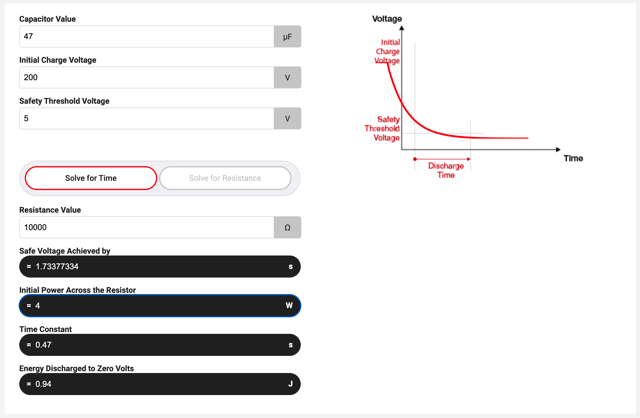
Plugging in my largest known power filter capacitor value (47uF), rounding up my largest observed voltage of 150v (200v), and picking a safe-to-me voltage left in the capacitor (5v), then finally playing with a resistance value, the calculation(s) will determine what resistor is good for you. Mine happened to be a 10k (10,000 ohm) 5w resistor which will discharge a 47uF capacitor with a stored energy voltage of up to a 200v down to 5v in ~1.7 seconds, while keeping resistor wattage consumption to absorb that discharge at 4w.
Do remember these are my MAXIMUM-SAFE calculations. With this resistor value, I could push this up to an observed 205/210v high voltage capacitor discharge scenario, however, that also drives the resistor wattage quite close to maximum range on the resistor (4.84w of 5w maximum).
Do remember if you decide to discharge a capacitor that is within the maximum voltage range but is larger than what you initially calculated your resistance value with (e.g. 100uF or 68uF vs 47uF), the time it takes to discharge increases.
Do remember if you decide to discharge a capacitor that is within the maximum voltage range but is smaller than what you initially calculated your resistance value with (e.g. 22uF or 1uF vs 47uF), the time it takes to discharge decreases.
Do remember at the end of any capacitor discharge, always remeasure the voltage (left) in your capacitor with a multi-meter.
If you are in doubt, PLEASE DO NOT SKIP THIS; just use the calculator. Going through this will help you better understand the most important item in the "Stuff" section (e.g. the resistor value) below vs. being overly diy-excited, then blindly hyper-following my step(s) to build a random capacitor discharge tool that may not fit your needs.
The "Stuff" You'll Need (I used)
Below is a list of parts I used. You might have this stuff around from previous projects, or not. YMMV.
- 10k 5w Cement Resistor
- Medium Alligator clips assortment with insulated boots
- (1) Alligator clip with Black boot
- (1) Alligator clip with Red boot
- Heat Shrink tubing kit
- PC Power Chord (3ft)
- Cut into (2) 18" pieces
- (Optional) Resistor housing (3D printed)
- You can cover this entirely with shrink tubing, post soldering, as an alternative
- (Optional) (4) #4 x 1/2" wood/metal screws (for attaching resistor housing lid)
- (Optional) (1) 5" piece of 10mm / 7/16" width velcro (to tie up alligator clip ends when not in use)
- (Optional) (1) 3/4" zip tie adhesive mount (bottom of resistor housing, fold/feed the velcro through it as a fastener)
Then as far as tool(s), at least this:
- Soldering iron
- Solder
- Heat gun (for shrink tubing)
- Flux + Tinning paste (for tinning the stranded core wire leads, soldering wire onto alligator clip, etc)
- Wire stripper
- Glue gun (for stress relief on wires)
- Needle-nose plyers (for bending tinned wire leads and crimping resistor lead ends and alligator clips)
The Build
We got the stuff, let's get this discharge tool build going!
The Resistor Housing (3d print)
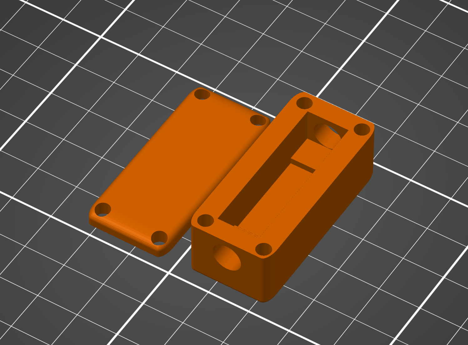
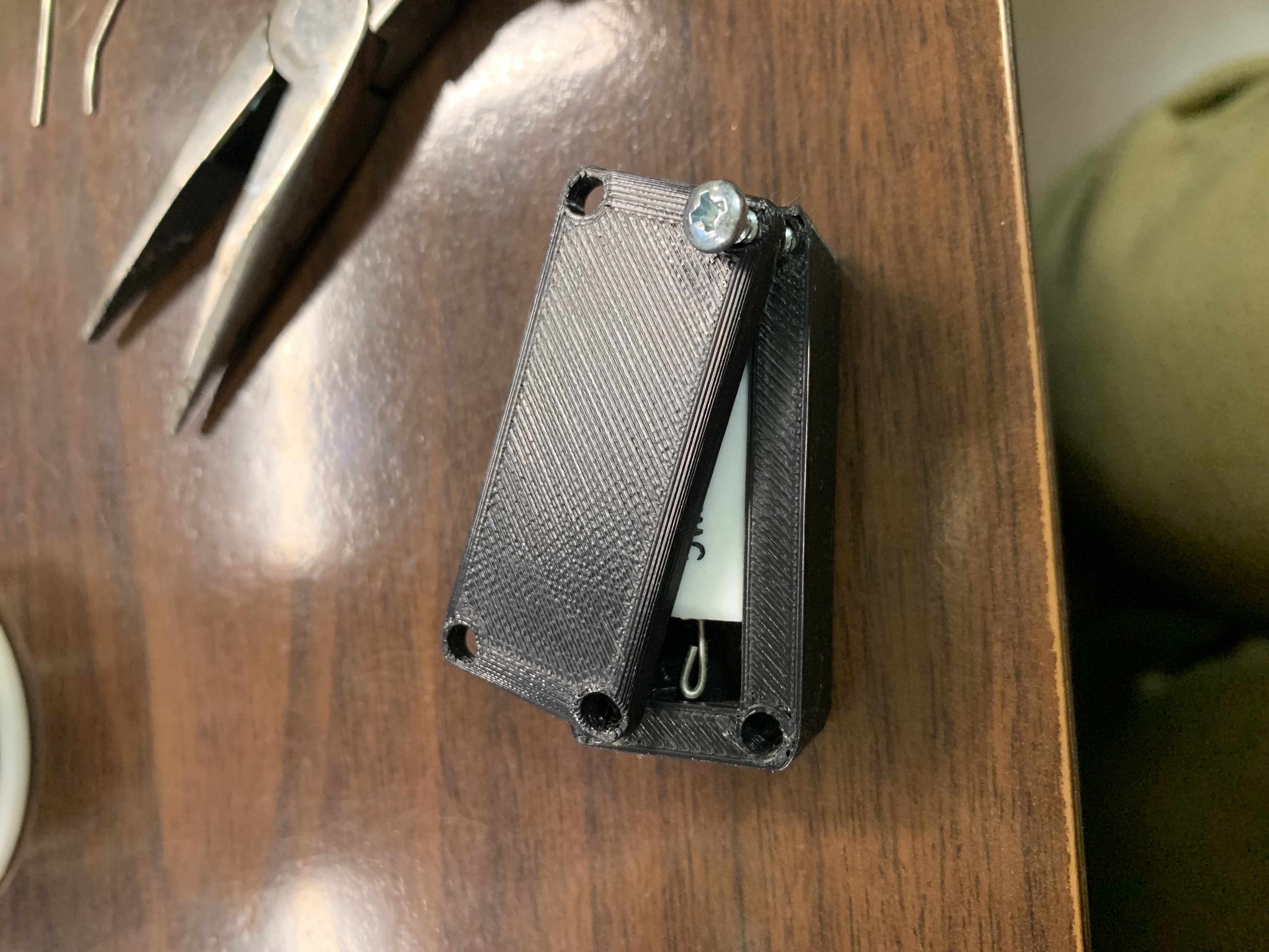
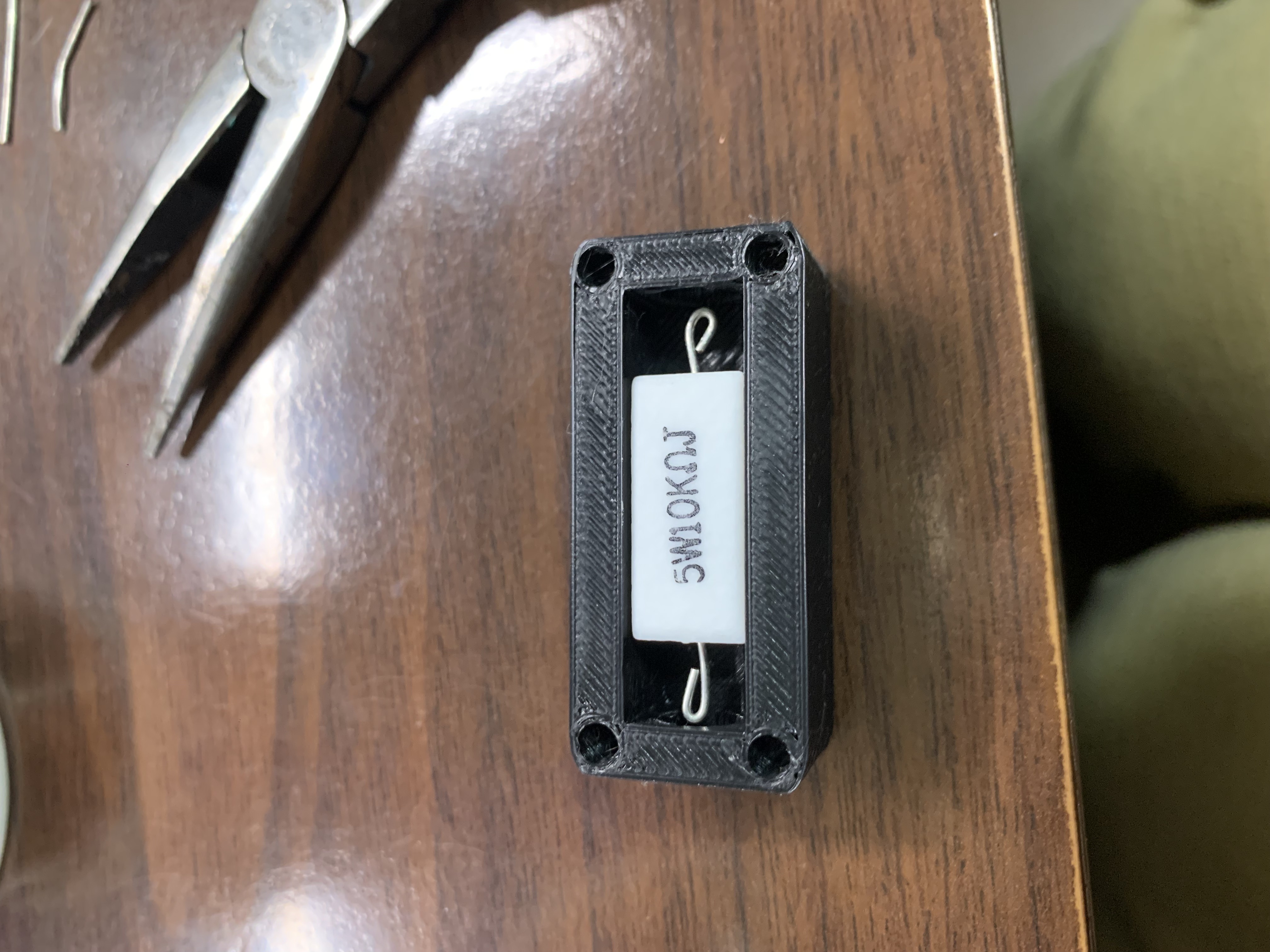
The resistor housing I modeled fits most 5w cement resistors I've got around of various resistance (10mm x 10mm x 22mm) with 7mm holes for the insulated PC power chord wire. There's a "cradle" the resistor sits in to compensate for movement.
Print settings of note:
- Infill: 25%
- Supports: Everywhere (box and lid are beveled)
|
The Discharge Tool Construction
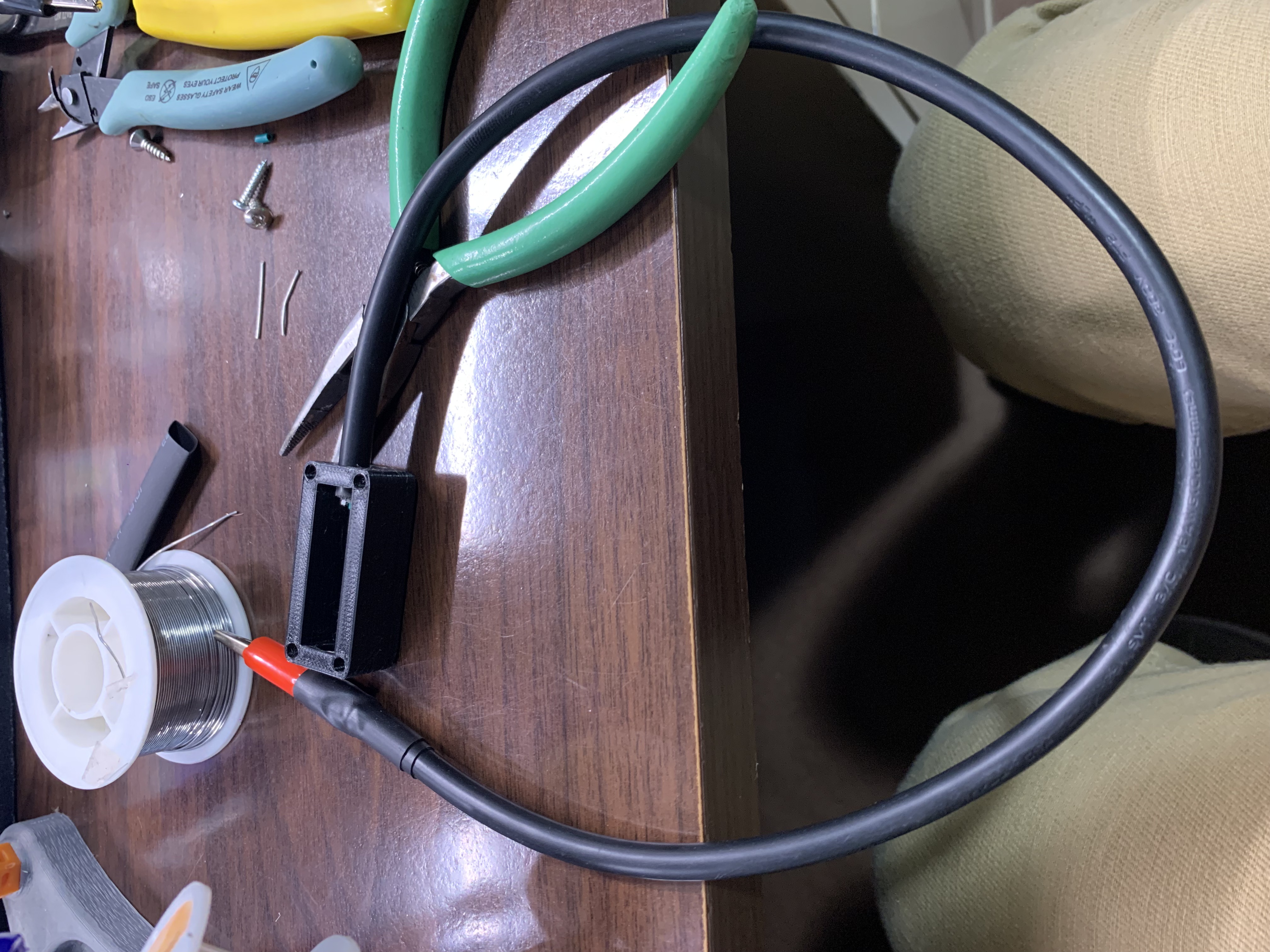
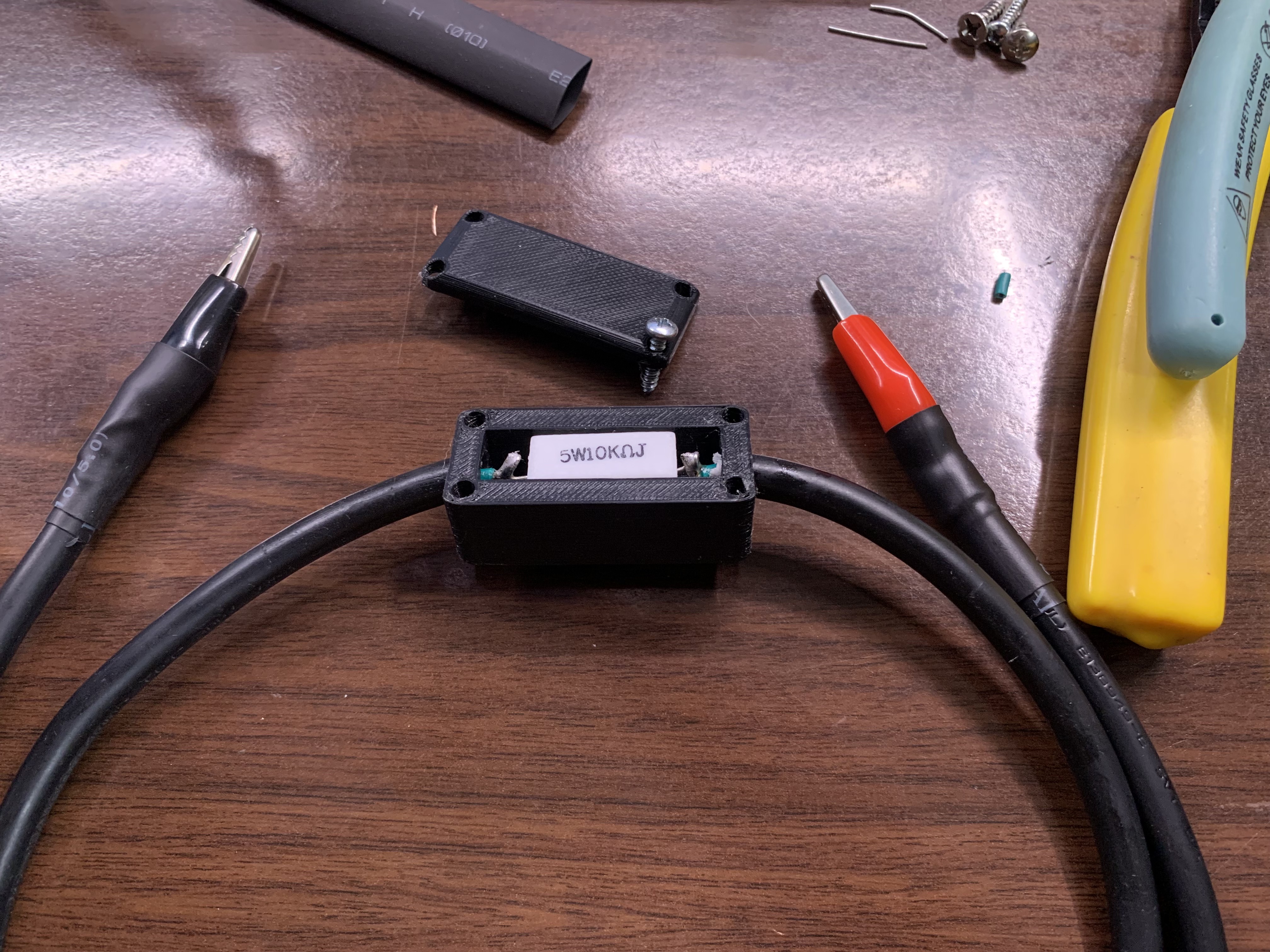
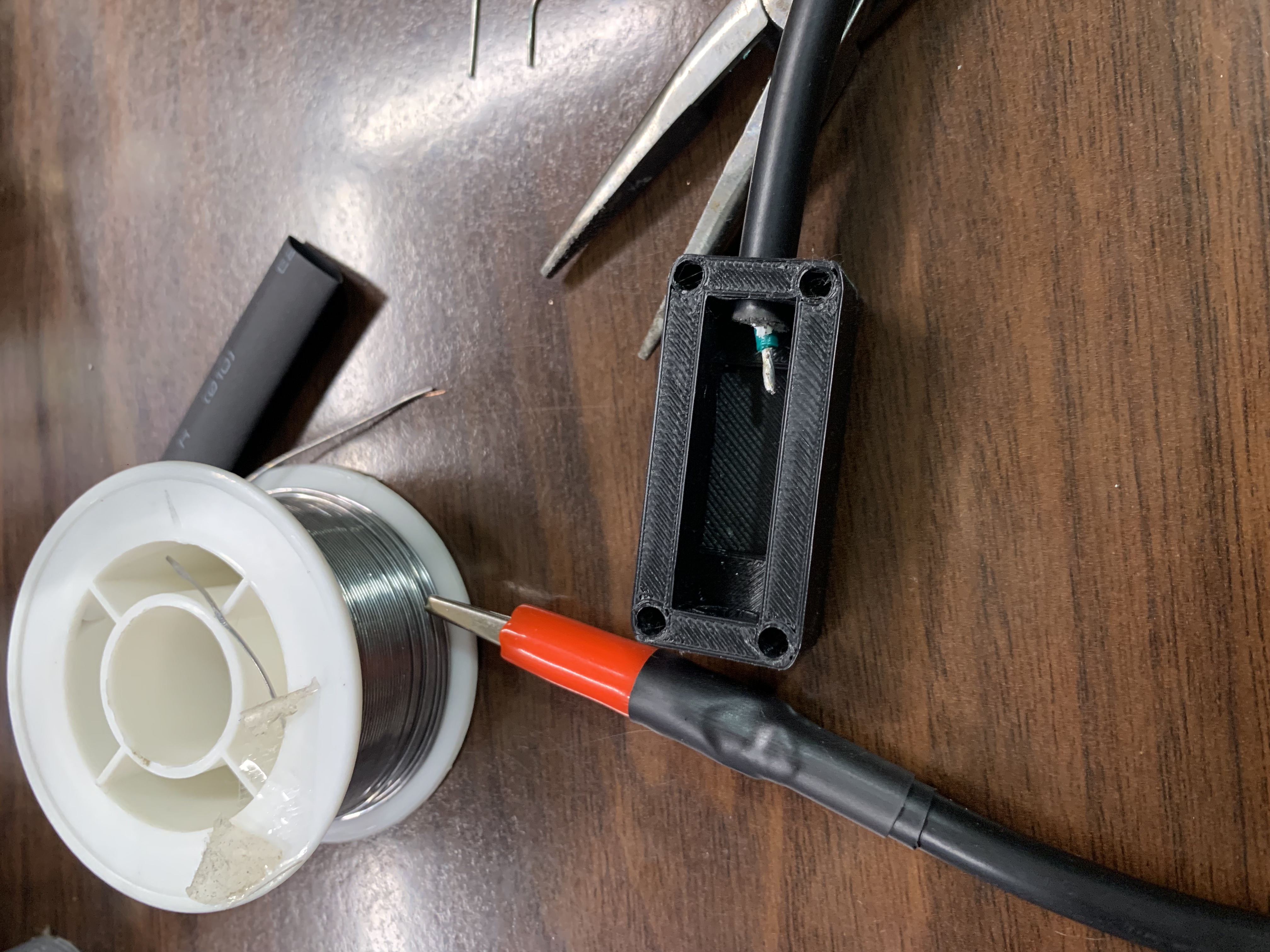
Assembling the capacitor discharge tool is fairly obvious. Let's make it simple and just insanely marginalize the effort here: It's a resistor between two pieces of insulated wire along with insulated (non-conductive) alligator clips at each end.
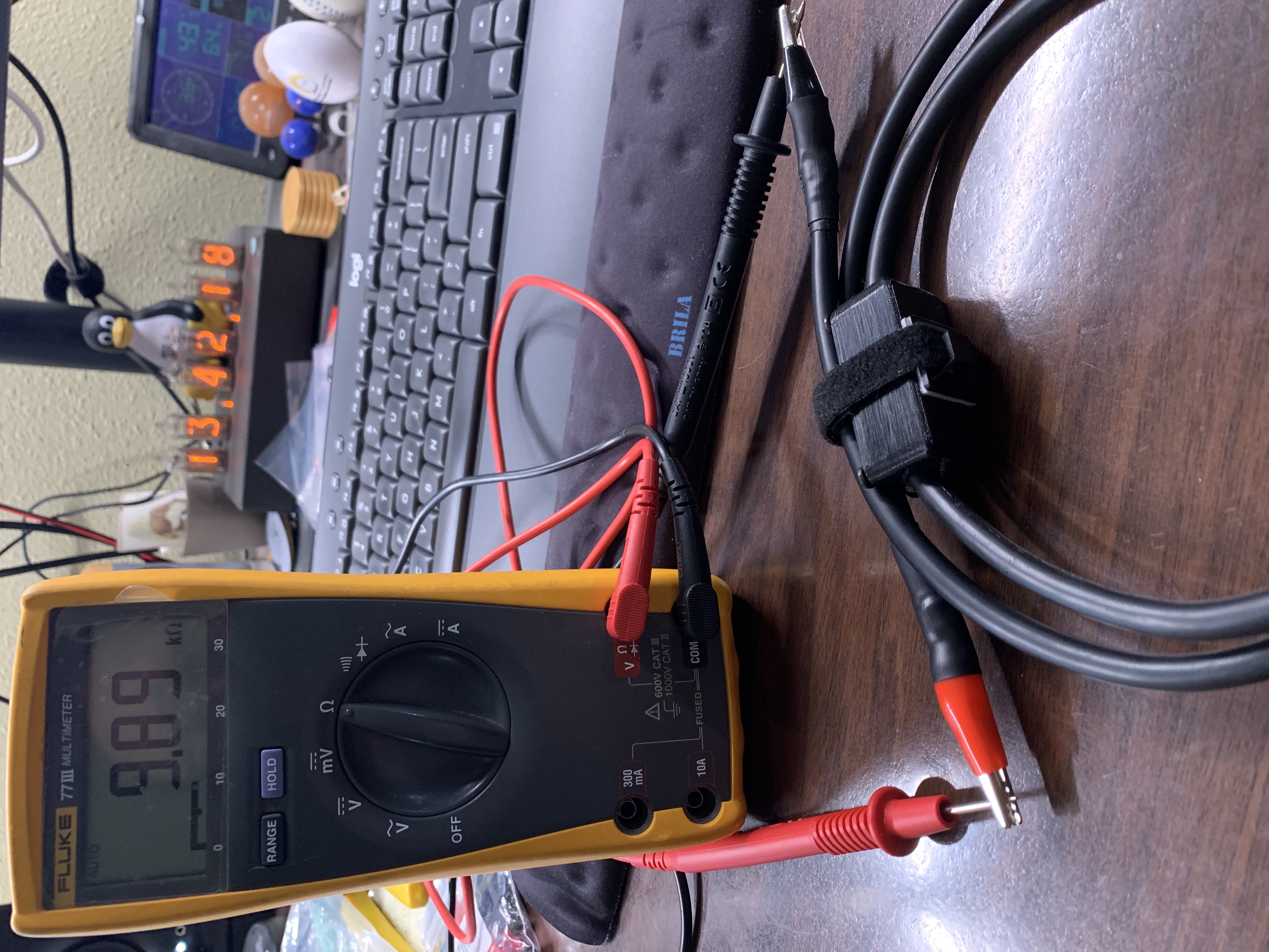
When you get it all assembled, the only things left to do prior to use with a multimeter is:
- Measure and confirm the resistance value in your cable.
- Perform a continuity test of your cable.
Below are the pictures that are fairly easy to follow what is going on and how to assemble:
|
|
|
|
|
|
That's it! You made it!
Now onto getting the Fender Blues Junior amp gently disassembled and accompanied parts in order and prepared to start the modifications!
Resources
- Capacitor Discharging Explained (learningaboutelectronics.com)
- Filter capacitor discharge procedure (mojotone.com)
- Constructing a capacitor discharge tool (ifixit.com)
- Capacitor Safety Discharge Conversion Calculator (digikey.com)
- Capacitor Bleeders (sound-au.com)